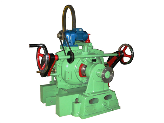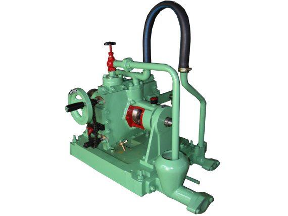

- Capacities for Testing Single Cylinder Engines and Max Up to 1000 HP Available
- Low Inertia Rotors
- Simple and Stable Operation
- Versions with Mechanical Seals available
- ATE-Series Dynamometers are designed for Universal Application in all Types of Testing like for Engines, Turbines, Motors, Components and PTO testing
- Calibration systems with levers and weights allow simple and precise adjustment and checking of the torque measuring chain, regardless of whether the brake is at standstill or rotating Stable Loading useful for Testing of Newly Assembled & Reconditioned Engines
- Extremely Reliable Machines to ensure long life with performance & accuracy
- No Need of High Speed PID Controllers and Servo-motors for Load Control
- Can be interfaced with Automatic Load Control and Data Acquisition System
We are Manufacturer, Supplier, Exporter of Sluice Gate Type Hydraulic Dynamometers from Kolhapur, Maharashtra, India.
| Model | Max Torque (N-m) | Max Power (bpm) |
| ATE-16 | 120 2000 to 5600 |
100 5600 to 8000 |
| ATE-60 | 339 1600 to 3600 |
169 3600 to 7500 |
| ATE-160 | 750 1500 to 2500 |
260 2500 to 6000 |
| ATE-305 | 1428 1000 to 2000 |
405 2000 to 5000 |
| ATE-705 | 3300 900 to 1600 |
750 1600 to 3500 |
| ATE-1500 | 7920 690 to 1330 |
1500 1330 to 2750 |
Application :
- Universal range of application for examinations on engines and engine assemblies
- Development of Petrol & Diesel engines for cars and commercial vehicles
- Development and testing of engine assemblies, e.g. Piostons, Ignition systems, Sealing, Filters, Carburetor and Fuel Injection equipment, Exhaust gas ducting and catalysts
- Quality Control
- Development and Testing of Fules and Lubricants
Advantage :
- Low Inertia Rotor
- Internals of Gun Metal ensure Long life without corrosion and erosion
- Bi-directional operation can be achieved by connecting the Prime-mover to be tested at either end
- Low Initial and Running Costs
- Lower level of expertise needed to operate these type of dynamometers
- Stable Load Control
Principle :
The dynamometer is fed with water under pressure. When the torridal space is filled with water and the impeller is rotated by the prime - mover, a torridal flow is established outward in the impeller and inward in the stator, which acts as a STALLED TURBINE. Due to the change in momentum experienced by the water in passing from rotating impeller to the stator blade-ring, the torque impressed on the water by the impeller is transferred to the stator. This torque tries to revolve the cradled power absorption unit in the same direction of the impeller.The lever arm attached to the Stator Casing is linked to the Weigh - Bridge. It prevents the rotation of the power absorption unit and transmits the load to the load meter.

